

STM32 / FPGA Board
I put together a development board of sorts last month to test out a few different things. It consists of a STM32F4 microcontroller with its external memory interface connected to a Xilinx Spartan-6 FPGA. The FPGA has a basic VGA output as well as SDRAM to use as a frame buffer. An ethernet PHY is also attached to the microcontroller. This project serves several purposes:
- More complex project to continue learning how to use OrCAD.
- Test bed for an architecture I'd like to use in the future where the STM32 FSMC is used to interface to an FPGA and map "registers" created in the FPGA into microcontroller memory space.
- Test board for DP83848 ethernet interface circuitry.
- Not originally planned, but my first try at assembly using solder paste and reflow.
This board isn't super complicated electrically, but took a while to design because I had to create new components and footprints for most of the parts. I have a decent parts library now, so this was a good use of time though.
The challenging part for this project was assembly. I was planning to hand solder it, but the timing lined up with when I started researching reflow soldering for another project. So I decided to order a stencil and use solder paste plus a toaster oven instead. Unfortunately, I didn't get a decent photo of the board before it was fully assembled, but there is a short video clip here of the reflow process. There were a couple mistakes I made in the process. Two components (SDRAM and SPI flash) did not have stencil openings because I forgot to define paste mask openings when creating the pads for those packages. A ton of the pins on the STM32 and FPGA also ended up bridged after reflow... likely due to me not holding the stencil down well enough and getting too much paste applied. Soldering the messed up parts by hand plus using lots of solder braid to clear the bridged pins resulted in the final result shown below.

After cleaning up all the soldering issues and getting to the point where the 3.3V rail and ground weren't shorted, I powered the board up. Fortunately, board bring-up went better than the soldering did. I was able to connect to the STM32 and the FPGA with their respective programming interfaces and verify that both were functional.
The only fail electrically was the clock source for the DP83848 ethernet PHY. The PHY requires its own 25 or 50 MHz clock source because the frequency is not a multiple of the 12 MHz crystal used for the micro. I placed a 25 MHz crystal to cover this. When reviewing the PHY datasheet before ordering parts, I discovered that in RMII mode (which I'm using) it needs a 50 MHz oscillator. A plain old crystal can only be used for 25 MHz clock when in full MII mode. I caught this and ordered a 50 MHz oscillator that fit the same footprint as the crystal I had designed the board for. Thought this solved the problem... kinda forgot that oscillators need power and ground though, which are not routed to it since I was going to use a crystal. Oh well, I'll have to bodge the oscillator in with some jumper wires before I can test ethernet.
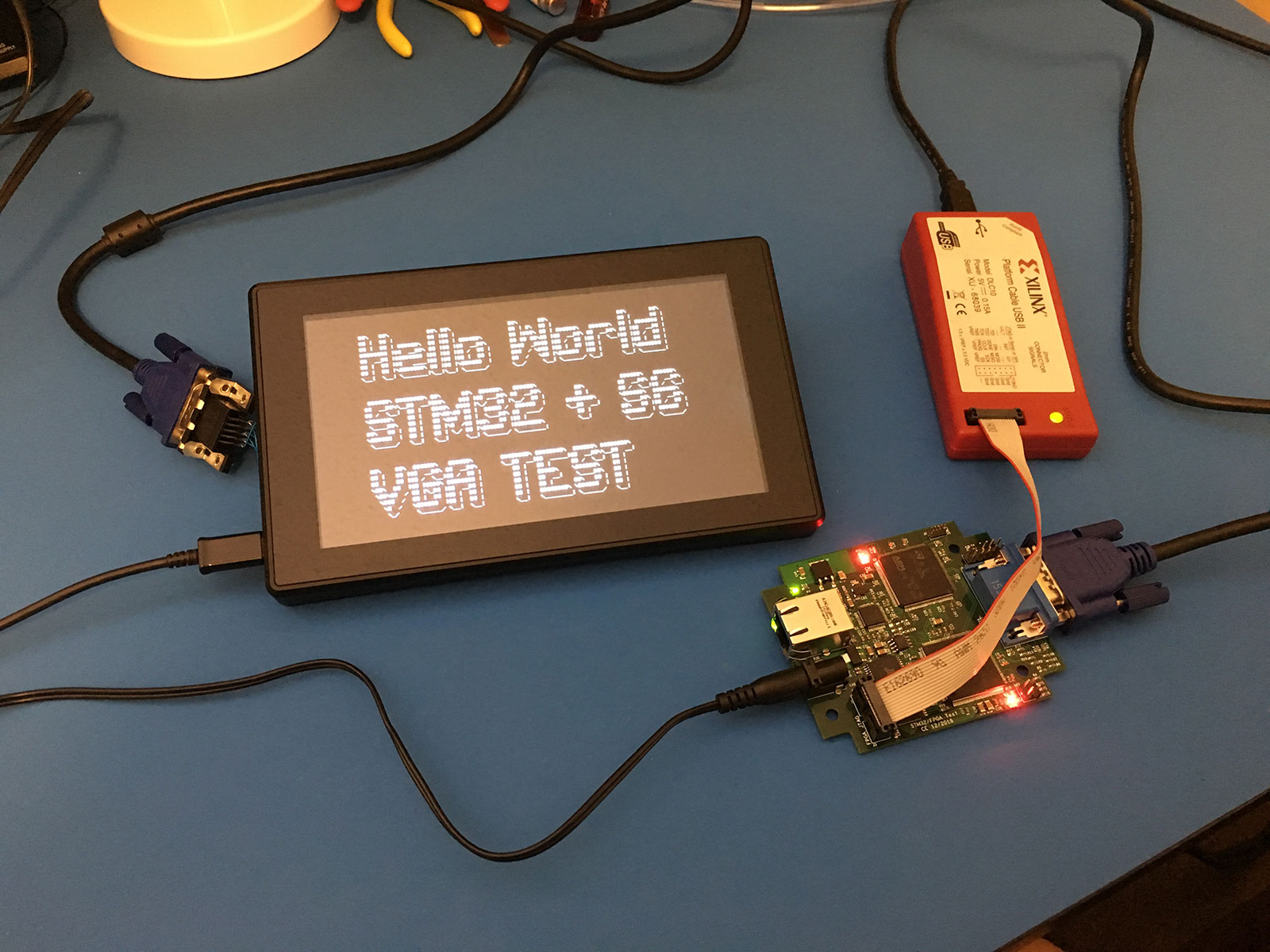
Software wise, at this point I have some basic test code running on the STM32 and text output on VGA working. I had a mostly working verilog design for VGA output from another project, so that didn't take long. It is purely text-based, using characters from a text buffer in block RAM to index into a "font ROM" which defines the pixels to display for each character. All that had to be added was a serial interface for writing to the text buffer RAM, so the STM32 could control what was displayed.
Next step from here is to build a controller to use the SDRAM chip on board. This is needed to have a full resolution frame buffer, as block ram in the FPGA is much too small to hold a full video frame. Until then, only text can be displayed. I have read a few articles and have a pretty good idea how this will work, but it is still a significant amount of verilog to write. After that, I need to get the FSMC (external memory interface) in the STM32 set up. Communication between the STM32 and FPGA is currently only a slow serial port. Ethernet needs to be tested too. I have working code for this from another project, so it should be easy once the oscillator is fixed.